MAKE A MEME
View Large Image

| View Original: | NE555 Bloc Diagram.svg (722x524) | |||
| Download: | Original | Medium | Small | Thumb |
| Courtesy of: | commons.wikimedia.org | More Like This | ||
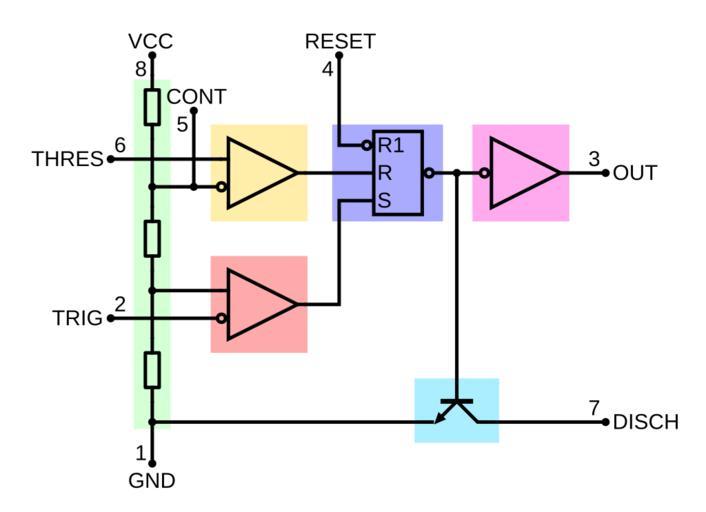
| Keywords: NE555 Bloc Diagram.svg The NE555 contains 24 bipolar transistors two diodes and 15 resistors that form six functional blocks Between the supply voltage VCC + and the ground GND - is a voltage divider consisting of three identical resistors which when connected not from the outside the two reference voltages ¹ / 3 VCC and ² / 3 VCC supplies The latter is at the terminal pin Control Voltage available The block diagram and schematic that area is highlighted in green Two comparators are each connected to one of the reference voltages while the other two inputs of which are fed directly to the terminals of trigger or threshold The block diagram in yellow and orange A flip-flop deposited in the color purple stores the state of the timer and is controlled by the two comparators Via the reset terminal overrides the other two inputs the flip-flop and therefore the entire timer device be reset at any time At the output of flip-flop followed by an output stage with totem-pole output that can be loaded at the port output with up to 200 mA Shown in the color pink Parallel to the output stage of a transistor is connected the collector is located on the discharge port The transistor in the circuit diagram is a light blue background always energized when the output is low level Der NE555 enthält 24 Bipolartransistoren zwei Dioden und 15 Widerstände die zusammen sechs Funktionsblöcke bilden Zwischen der Versorgungsspannung V<sub>CC</sub> + und der Masse GND ˆ’ befindet sich ein Spannungsteiler aus drei identischen Widerständen der wenn nicht von außen beschaltet die beiden Referenzspannungen ¹/<sub>3</sub> V<sub>CC</sub> und ²/<sub>3</sub> V<sub>CC</sub> liefert Letztere ist am Anschluss-Pin Control Voltage verfügbar Im Blockdiagramm und Schaltplan ist jener Bereich grün hinterlegt Zwei Komparatoren sind jeweils mit einer der Referenzspannungen verbunden während die beiden anderen Eingänge direkt auf die Anschlüsse Trigger bzw Threshold geführt sind Im Blockdiagramm gelb und orange hinterlegt Ein Flipflop in der Farbe lila hinterlegt speichert den Zustand des Timers und wird über die beiden Komparatoren angesteuert à ber den Reset-Anschluss der die beiden anderen Eingänge übersteuert kann das Flipflop und damit der gesamte Timer-Baustein jederzeit zurückgesetzt werden Am Ausgang des Flipflops folgt eine Ausgangsstufe mit Totem-Pole-Ausgang die am Anschluss Output mit bis zu 200 mA belastet werden kann In der Farbe Rosa dargestellt Parallel zur Ausgangsstufe ist ein Transistor angeschlossen dessen Kollektor am Anschluss Discharge liegt Dieser Transistor im Schaltplan hellblau hinterlegt ist immer dann durchgeschaltet wenn der Ausgang Low-Pegel hat Own 2007-09-23 BlanchardJ thumb left Bipolar circuit diagramthumb left CMOS circuit diagram Created with Inkscape ElCompLib 555 timer IC | ||||