MAKE A MEME
View Large Image

| View Original: | Crystal radio with impedance matching.svg (601x379) | |||
| Download: | Original | Medium | Small | Thumb |
| Courtesy of: | commons.wikimedia.org | More Like This | ||
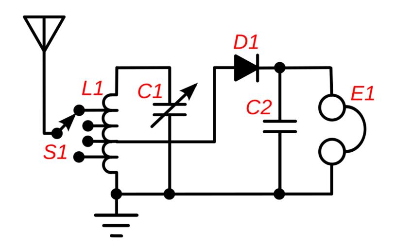
| Keywords: Crystal radio with impedance matching.svg A crystal radio receiver circuit that uses impedance matching to increase the power transferred from the antenna through the receiver to the earphone E1 This type of circuit was used in higher quality radios around 1920 Maximum power is transferred from one circuit to another when their impedance resistance is equal However in a crystal receiver the impedance of the antenna-ground circuit around 10-200 ohms is far less than the impedance of the tuned circuit L1 C1 thousands of ohms at resonance and varies depending on the length of the antenna etc Therefore the antenna is connected to a tap across only a portion of the coil's turns using a multiposition switch S1 This makes the tuning coil L1 act as an impedance matching autotransformer in addition to its tuning function transforming the high impedance of the tuned circuit down by the square root of the turns ratio to match the antenna The switch S1 is adjusted until the radio station is loudest in the earphone <br> The impedance of the crystal detector D1 is also matched to the tuned circuit by connecting the detector like the antenna to a tap on the coil In addition to improving power transfer impedance matching also improves selectivity of the receiver its ability to reject interfering signals at nearby frequencies by reducing the resistive loading of the tuned circuit increasing the Q factor <br> The blocking capacitor C2 filters the radio frequency pulses out of the rectified output of the detector It can often be omitted since the earphone cord usually has sufficient capacitance own 2010-05-18 Chetvorno I User Chetvorno the author of this drawing release it into the public domain for any use whatever Crystal radios | ||||